
Pressure Switch Diagram
LK Die Casting Machine / 2024-10-04 11:38:48
2024-09-29 by Cherry
Introduction
As an important metal forming equipment in modern
industrial production, the stability, and accuracy
of the die-casting machine's operation is crucial
to produce high-quality castings.
The pressure switch diagram plays a key role in the
control system of the die-casting machine. It can monitor
and control the pressure changes in the die-casting
process in real time to ensure the die-casting machine's
normal operation and the castings' quality.
This article will explore the application of pressure
switch diagram in the die-casting machine in-depth,
including its working principle, functional characteristics,
specific application in different links of the die-casting
machine, and its important significance to die-casting
production.
Basic principles and composition of the pressure
switch diagram
The working principle of the pressure switch
The pressure switch is an automatic control device that
controls the on and off of the circuit according to the
pressure change. It is used to monitor and adjust the
pressure in the system. When the pressure reaches the set
value, the switch triggers the corresponding control
signal to start or stop the operation of the equipment.
It usually contains an elastic element, such as a spring
or a diaphragm, which will cause deformation when the
pressure acts on the elastic element. As the pressure
changes, the degree of deformation of the elastic component
will also change accordingly.
When the pressure reaches the set threshold, the deformation
of the elastic element triggers a mechanical or electronic
switch action, thereby realizing the on-off switching of
the circuit. In the die-casting machine, the pressure
switch controls the operation and stop of related equipment
by monitoring the pressure changes in the hydraulic system.
The basic principle of the pressure switch can be summarized
as follows:
1. Pressure sensing: The pressure switch senses the pressure
changes in the system through the internal sensor.
2. Signal processing: When the pressure reaches the set threshold,
the sensor transmits the signal to the control system.
3. Execution control: The control system performs corresponding
operations based on the received signal, such as starting
or shutting down the pump or valve of the die-casting machine.
This automated control makes the die-casting process more
precise and reduces the possibility of human intervention.
Constituent elements of the pressure switch diagram
The pressure switch diagram is mainly composed of pressure
sensors, signal processing circuits, comparators, and
output circuits. The pressure sensor is responsible for
real-time detection of the pressure in the hydraulic system
and converting the pressure signal into an electrical signal.
The signal-processing circuit amplifies and filters the
electrical signal output by the sensor to improve the quality
and stability of the signal.
The comparator compares the processed pressure signal with
the preset pressure threshold and outputs the corresponding
control signal when the pressure exceeds or falls below the
threshold. The output circuit drives the relevant actuators,
such as relays, solenoid valves, etc., according to the
output signal of the comparator to realize the control of
the die-casting machine equipment.
Functional characteristics of pressure switch diagram in
die-casting machine
1. Accurate pressure monitoring and control
The pressure switch diagram can monitor the pressure
changes in the hydraulic system of the die-casting machine
in real time and accurately. By presetting a suitable
pressure threshold, it can be ensured that the pressure
in the die-casting process is always kept within the
specified range.
This is crucial to ensure the quality and dimensional
accuracy of the casting. For example, during the injection
process, the injection pressure needs to be accurately
controlled to ensure that the molten metal can fill the
mold cavity and will not cause mold damage or defects
such as a flash on the casting due to excessive pressure.
The precise control function of the pressure switch diagram
can effectively achieve this goal and improve the qualified
rate of castings.
2. Fast response and stability
During the working process of the die-casting machine, the
pressure changes very quickly, especially in the injection
and pressure-holding stages. The pressure switch diagram has
the characteristics of fast response can detect the pressure
change in time, and quickly outputs the control signal so
that the related equipment of the die-casting machine can
make timely adjustments.
At the same time, it also has good stability, can maintain
accurate pressure monitoring and control during long-term
working processes, and is not affected by external interference
and system fluctuations. This provides a reliable guarantee
for continuous and stable operation of the die-casting
machine.
3. Multiple pressure control modes
The pressure switch diagram usually supports multiple pressure
control modes to meet the needs of different working links
of the die-casting machine. For example, it can realize the
constant pressure control mode, that is, keep the pressure
constant throughout the die-casting process; it can also realize
the variable pressure control mode, according to the requirements
of the die-casting process, and set different pressure values
at different stages.
This flexible pressure control mode enables the die-casting
machine to adapt to various complex casting production processes
and improves the versatility and adaptability of the die-casting
machine.
4. Fault diagnosis and alarm function
The pressure switch diagram also has fault diagnosis and alarm
functions. When the pressure in the hydraulic system changes
abnormally, such as too high or too low pressure, too large
pressure fluctuations, etc., it can detect and send an alarm
signal in time to remind the operator to check and deal with
it. At the same time, by analyzing the pressure change trend,
the cause and location of the fault can be preliminarily
determined, providing effective reference information for
maintenance personnel, shortening troubleshooting time,
reducing equipment downtime, and improving production
efficiency.
Application of pressure switch diagram in different
links of die-casting machine
1. Application in mold closing process
During the mold-closing process of the die-casting machine, it
is necessary to provide sufficient mold closing force to
ensure the tight closure of the mold and prevent metal liquid
leakage. The pressure switch diagram monitors the pressure of
the mold closing hydraulic system and controls the action
of the mold-closing cylinder to ensure that the mold-closing
force reaches the set value.
When the mold closing force is insufficient, the pressure
switch will send a signal to prompt the hydraulic system to
increase the pressure until the mold closing force meets
the requirements. Conversely, when the mold closing force
is too large, it will be adjusted in time to avoid damage
to the mold and equipment. This ensures that the mold can
maintain a good sealing state during each die-casting
process, providing a basic guarantee of the quality of the
casting.
2. Application in the injection process
The injection process is the core link of the die-casting machine,
and the control of pressure directly affects the molding
quality of the casting. The pressure switch diagram plays a vital
role in the injection process. It monitors and controls the
pressure of the injection cylinder in real-time according to
the preset injection pressure curve. At the beginning of
injection, a lower pressure is required to push the molten
metal to fill the runner.
As the molten metal gradually approaches the mold cavity,
the pressure gradually increases to ensure that the molten metal
can fill the cavity at a sufficient speed and pressure to
avoid defects such as pores and looseness. During the
pressure-holding stage, the pressure switch diagram
continues to maintain a certain pressure to compensate for the
shrinkage of the molten metal during the cooling process and
prevent shrinkage holes and shrinkage problems in the casting.
Through precise pressure control, the pressure
switch diagram can ensure the smooth progress of the injection
process and produce high-quality castings.
3. Application in the pressure-holding process
The pressure-holding process is to maintain a certain pressure for
some time after the molten metal fills the mold cavity. The purpose
is to compensate for the volume shrinkage of the molten metal
during the cooling and solidification process and ensure the
dimensional accuracy and internal quality of the casting. The
pressure switch diagram strictly controls the size and time of
the pressure holding pressure during the pressure holding process.
It presents a reasonable pressure holding pressure and time
according to factors such as the material, shape, and size of
the casting. During the pressure holding period, the pressure
changes are monitored in real-time. Once the pressure drops below
the set value, the hydraulic system will be started in time to
supplement the pressure to maintain a stable pressure-holding
state.
After the pressure holding is completed, the pressure
switch diagram controls the hydraulic system to release the
pressure and prepare for the mold opening. Accurate pressure
holding control is one of the keys to obtaining high-quality
castings, and the pressure switch diagram plays an indispensable
role in this process.
4. Application in the demolding process
The demolding process is the link of removing the molded casting
from the mold. During the demolding process, appropriate demolding
force is required to ensure that the casting can be smoothly
separated from the mold without causing damage to the casting and
the mold. The pressure switch diagram monitors the pressure of the
demolding hydraulic system and controls the action of the demolding
cylinder to achieve precise control of the demolding force.
When the demolding force is too large, it may cause deformation or
damage to the casting; when the demolding force is too small, the
casting may not be de-molded smoothly. The application of the
pressure switch diagram can ensure that the demolding force is
within the appropriate range, and improve the success rate of demolding
and the quality integrity of the casting.
When designing the pressure switch system of a die-casting machine,
multiple factors need to be considered:
1. Select the appropriate pressure range
According to the working characteristics of the die-casting machine,
select the appropriate pressure range to ensure that the switch
can accurately respond to pressure changes.
2. High temperature and corrosion resistance
Due to the presence of high temperature and molten metal in the
die-casting process, the material and structure of the pressure
switch must have high temperature and corrosion resistance to
ensure long-term stable operation.
3. Sensitivity and response time
The sensitivity and response time of the switch directly affects
the safety and efficiency of the die-casting process. When designing,
it is necessary to ensure that it has high sensitivity and fast
response capabilities.
Installation and debugging of the pressure switch diagram
1. Selection of installation position
The installation position of the pressure switch on the die-casting
machine should be determined according to the layout of the
hydraulic system and the requirements of pressure monitoring.
Generally speaking, a position that can accurately reflect the
changes in system pressure should be selected in the hydraulic
pipeline, usually installed at key locations such as the oil
pump outlet, the injection cylinder inlet, and the mold closing
cylinder inlet.
At the same time, the convenience of installation and the operability
of maintenance should be taken into account to ensure that the
pressure switch is easy to install, disassemble, and debug.
During the installation process, it is also necessary to avoid
the pressure switch from being affected by external mechanical
damage, vibration, high temperature, and other factors to ensure
its normal operation and measurement accuracy.
2. Debugging steps and methods
After the installation is completed, the pressure switch
diagram needs to be debugged to ensure that it can accurately
monitor and control the pressure. The debugging steps are
as follows:
1. Pressure sensor calibration: First, use a standard pressure
source to calibrate the pressure sensor to ensure that there
is an accurate correspondence between the electrical signal
output by the sensor and the actual pressure value. During
the calibration process, follow the instructions of the
pressure sensor to adjust the calibration parameters so that
the output error of the sensor under different pressures is
controlled within the allowable range.
2. Set the pressure threshold: According to the process requirements
and operation manual of the die-casting machine set the
pressure threshold of each working link. These thresholds should
be reasonably determined based on factors such as the material,
shape, size of the casting, and the performance parameters of
the die-casting machine.
For example, the mold closing pressure threshold, the injection
starting pressure threshold, the injection peak pressure threshold,
the holding pressure threshold, etc. When setting the threshold,
full consideration should be given to the safe operation of
the equipment and the guarantee of the casting quality, and
a certain adjustment margin should also be left so that fine-tuning
can be performed as needed in actual production.
3. Functional test: After completing the pressure threshold
setting, perform the functional test of the pressure switch
diagram. Start the die-casting machine, and simulate each working
link, and observe the response of the pressure switch diagram
under different pressures. Check whether the pressure switch
can accurately output the control signal when the pressure
reaches the set threshold and drives the relevant equipment to
act.
At the same time, check whether the pressure display
is accurate and whether the error with the actual pressure
value is within the allowable range. During the functional
test, pay attention to recording various data and abnormal
conditions for timely analysis and processing.
4. System joint debugging: After the pressure switch diagram
is tested separately and the function is normal, the entire
control system of the die-casting machine is jointly debugged.
The pressure switch diagram is tested for coordinated work
with other parts such as the clamping mechanism, injection
mechanism, hydraulic system, and electrical control system
to ensure that the pressure switch diagram can work seamlessly
with other equipment during the actual operation of the
die-casting machine to achieve precise control of the die-casting
process.
During the joint debugging process, the various performance
indicators of the die-casting machine should be fully tested,
such as clamping force, injection speed, casting quality, etc.,
and the parameters and settings of the pressure switch diagram
should be further adjusted according to the test results
to achieve the best working state.
Precautions
During the installation and debugging of the pressure switch
diagram, the following matters should also be noted:
1. Reliability of electrical connection: Ensure that the electrical
connection between the pressure switch and the control system
is firm and reliable to avoid problems such as poor contact
and short circuit. Use wires and connectors that meet the
specification requirements, and perform wiring and wiring by
the electrical installation specifications.
2. Waterproof and dustproof measures: Since the working environment
of the die-casting machine is usually harsh, there are oil
stains, dust, and moisture. Therefore, effective waterproofing and
dustproof measures should be taken to protect the pressure
switch and related equipment from pollution and damage.
The pressure switch can be protected by sealants, protective
covers, etc. to ensure that it can still work normally in
harsh environments.
3. Safe operation: During the debugging process, the safety
operating procedures must be strictly followed to prevent
equipment damage or casualties caused by misoperation.
When debugging the hydraulic system, pay attention to
releasing the pressure to avoid danger caused by high-pressure
oil spraying.
At the same time, ensure that the debugging personnel
have relevant professional knowledge and skills
and are familiar with the working principle and operation
method of the die-casting machine and the pressure switch
diagram.
Maintenance and care of the pressure switch diagram
1. Regular inspection and cleaning
In order to ensure the normal operation of the pressure
switch diagram, it is necessary to inspect and clean it
regularly. The inspection content includes whether the
appearance of the pressure sensor is damaged, whether the
connection line is loose, whether the plug is in good
contact, etc.
At the same time, the surface of the pressure sensor
and the pressure switch should be cleaned regularly
to remove impurities such as oil, dust, etc. to ensure
the accuracy of pressure detection. You can use a clean
soft cloth or a special cleaning agent for cleaning, but
be careful to avoid using highly corrosive chemicals to
avoid damaging the equipment.
2. Calibration and verification
The accuracy of the pressure sensor will drift over time
and the use environment, so it is necessary to calibrate
and verify it regularly. The calibration cycle is generally
determined according to the frequency of use and accuracy
requirements of the equipment, usually once every six
months to one year.
During the calibration process, use a standard pressure
source and a high-precision measuring instrument, and
operate according to the prescribed calibration method
to ensure that the output error of the pressure sensor
is within the allowable range. If the accuracy of the
pressure sensor is found to exceed the standard, it
should be adjusted or replaced in time.
Troubleshooting and repair
When the pressure switch diagram fails, it should be checked
and repaired in time. Common faults include inaccurate
pressure display, inoperative pressure switch, abnormal
control signal, etc. For these faults, you can follow the
steps below to troubleshoot:
1. Check the power supply: First check whether the power
supply of the pressure switch diagram is normal, including
whether the voltage is stable and whether the power cord
is well connected. If there is a problem with the power supply,
it may cause the equipment to not work properly or abnormal
signals to appear.
2. Check the pressure sensor: Remove the pressure sensor from
the hydraulic system and use a multimeter or other tools
to detect whether its resistance value, the output electrical
signal, and other parameters are normal. If the pressure
sensor is damaged, a new sensor should be replaced in time.
3. Check the signal processing circuit and comparator:
Check the signal processing circuit and comparator to
see if there are any problems such as component damage
and loose solder joints. If a fault is found, the
corresponding circuit board should be repaired or replaced.
4. Check the connection line and plug: Check whether the
connection line between the pressure switch diagram and
other equipment is open, short, or poorly contacted,
especially the plug and socket. Replug the connection
line to ensure a reliable connection.
5. Check the mechanical parts: For the mechanical parts
of the pressure switch, such as springs, diaphragms, etc.,
check whether there is deformation, damage, or jamming.
If there is a problem with the mechanical parts, they
need to be repaired or replaced.
When troubleshooting and repairing, be sure to record the
fault phenomenon, troubleshooting process and repair
results for future reference and experience summary. At
the same time, for some complex faults, if you cannot
solve them yourself, you should contact a professional
maintenance personnel for repair in time to avoid
further damage to the equipment due to misoperation.
Spare parts management
To ensure the timely repair and replacement of
the pressure switch diagram, a spare parts management
system needs to be established. According to the model
and specifications of the equipment, reserve a certain
number of commonly used spare parts, such as pressure sensors,
signal processing circuit boards, relays, etc.
At the same time, spare parts should be classified as managed,
well marked, and recorded to ensure the quality and availability
of spare parts. Spare parts should be inspected and maintained
regularly to prevent them from being damaged or failing due to
long-term storage. When replacing spare parts, pay attention to
selecting spare parts of the same model and specification as
the original equipment to ensure compatibility
and stability of the equipment.
Case analysis of pressure switch diagram application
1. Case 1: Improving the quality of castings
During the production process, a die-casting company
found that some castings had quality problems such as
internal pores and shrinkage holes, which seriously affected
the product's pass rate and performance. After a comprehensive
analysis of the die-casting process and equipment, it was
found that this was caused by unstable pressure control
during the injection process.
The company introduced a pressure switch diagram control
system to monitor and accurately control the injection
pressure in real-time. By adjusting the parameters of the
pressure switch, the injection pressure changes according
to the preset curve, ensuring that the pressure of the molten
metal during the filling of the cavity and the pressure-holding
process is always kept within a reasonable range.
After a period of operation, defects such as pores and shrinkage
holes inside the castings were significantly reduced, the
product qualification rate was greatly improved,
and the mechanical properties of the castings were also
significantly improved.
2. Case 2: Optimizing production efficiency
During the production process, another die-casting
company found that the die-casting machine had a long
mold closing time, which affected the overall production
efficiency. Through inspection and analysis of the mold
closing the hydraulic system, it was found that the mold
closing pressure control was inaccurate, resulting in
multiple pressure adjustments during the mold closing
process to achieve the appropriate mold closing force.
The company installed a pressure switch diagram and optimized
the mold closing pressure threshold. By accurately controlling
the mold closing pressure, the mold closing process is smoother,
reducing the mold closing time and the number of adjustments.
In addition, the fault diagnosis function of the pressure switch
diagram can also timely detect potential problems in the mold
closing system, performing maintenance and processing in advance,
and avoid downtime caused by equipment failure. After the
improvement, the production efficiency of the die-casting machine
has been significantly improved, bringing considerable economic
benefits to the company.
Conclusion
As an important part of the die-casting machine control system,
the pressure switch diagram plays a vital role in the operation
of the die-casting machine and the casting production process.
It ensures the stability and accuracy of the pressure in each
working link of the die-casting machine through precise pressure
monitoring and control, rapid response, multiple pressure control
modes, fault diagnosis, and alarm functions, thereby ensuring the
quality, dimensional accuracy, and production efficiency of the
castings.
In practical applications, according to the specific situation
of the die-casting machine, the pressure switch diagram should
be reasonably selected and installed, debugged, and maintained
correctly to give full play to its advantages.
With the continuous advancement of science and technology
and the continuous development of die-casting technology,
the technology of pressure switch diagrams will continue to
innovate and improve, providing stronger support for the
development of the die-casting machine industry.
It is hoped that this article's detailed introduction
to the application of pressure switch diagrams in die-casting
machines can provide useful reference and reference for relevant
practitioners, and promote the continuous advancement of
die-casting machine technology and the high-quality development
of the industry.
We are LK Die die-casting machine Authorized Official Agent
for Egypt(EGY),Saudi Arabia(KSA),United Arab Emirates(UAE)
The Islamic Republic of Iran(Iran),Qatar(QAT),
The State of Kuwait(Kuwait), The Middle East
Contact us to discuss the details of your project and we'll
be happy to provide you with a review and quote.
Learn more about our die-casting services through:
https://www.zazdiecasting.com/ and https://ae.zazdiecasting.com/
OTHER CONTENT
-

2024-09-19 14:16:15 LK Cold Chamber Die Casting Machine DCC900 Locking Force: 9000KN Die Height: 400-1000mm Space Between Tie Bars: 930x930mm Shot Weight: 13.5Kg Casting Area Max:2250c㎡
More -
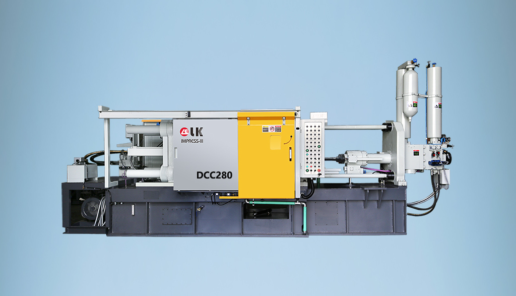
2024-09-19 14:11:06 LK Cold Chamber Die Casting Machine DCC280 Locking Force: 2800KN Die Height: 250-650mm Space Between Tie Bars: 560x560mm Shot Weight: 2.9Kg Casting Area Max:700c㎡
More -

2024-09-19 10:23:07 LK Cold Chamber Die Casting Machine DCC580 Locking Force: 5000KN Die Heigh: 350-850mm Space Between Tie Bars: 760x760mm Shot Weight: 6.9Kg Casting Area Max:1250c㎡
More -
2024-09-19 10:11:20 LK Cold Chamber Die Casting Machine DCC400 Locking Force: 4000KN Die Height: 300-700mm Space Between Tie Bars: 669x669mm Shot Weight: 4.7Kg Casting Area Max:1000c㎡
More